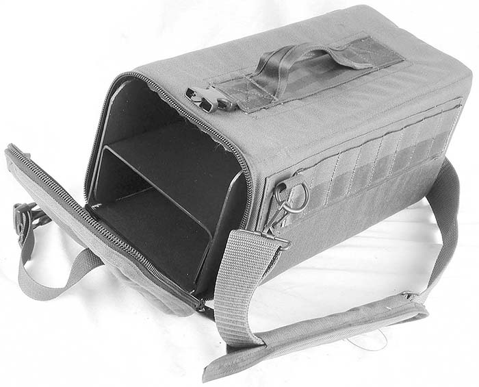
M60 Diagram Feed Tray and Hanger
THE CIVILIAN M60 MACHINEGUN OWNERS GUIDE: PART V
By Thomas T. Hoel, historical and technical editing by Dan Shea, Photos by Dan Shea
The M60 ammunition-feeding group is perhaps the most commonly damaged sub-system of the entire weapon. This is not usually due to the basic design of the feed system and the construction of its component parts, but rather, almost entirely the result of overtly abusive actions by the operator, or more commonly, a fundamental lack of understanding of those actions that may be damaging to these parts. As these component parts are invariably more expensive to fix or replace, an understanding of their handling, use, and operation will go a very long way toward extending their service life.
The M60 feed system is comprised of three primary component assemblies. The feed cover (or "top cover"), unit works in conjunction with the feed tray assembly to feed, guide, and contain the ammunition belt as it enters the weapon. Additionally, the bolt's cartridge stripping lug and the feed cam actuator ("bolt roller") assembly operating on the rear portion of the bolt body serve to both drive the feed cover mechanism, and actually strip and feed the individual cartridges from the unitized link belt. While these latter parts are actually components of the operating system group discussed above, they are also integral to the feed system too.
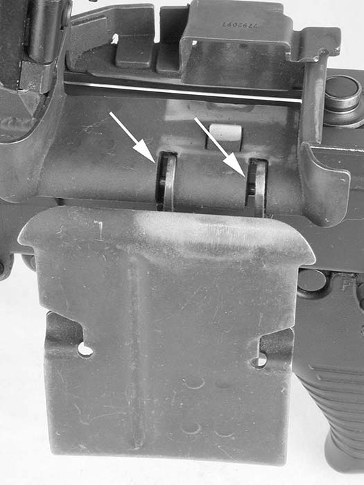
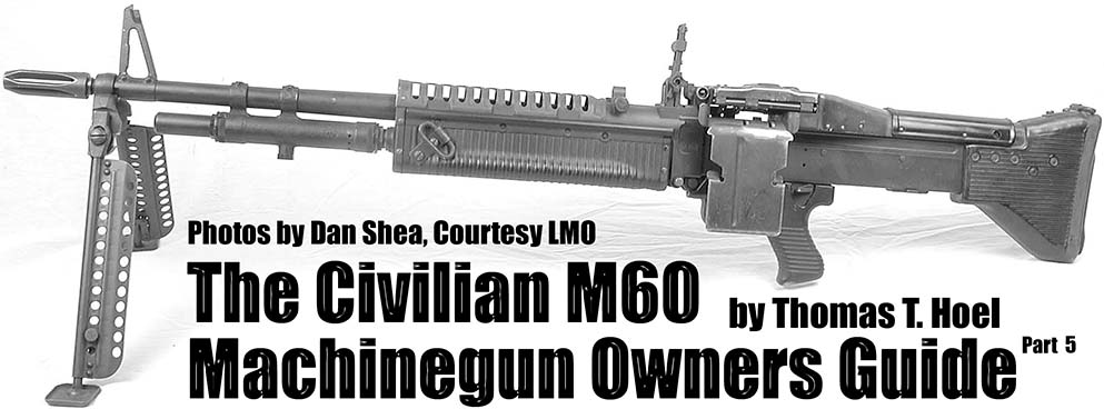
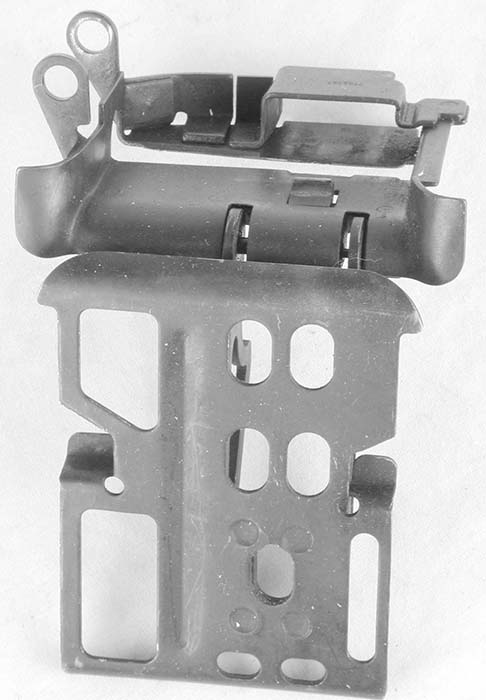
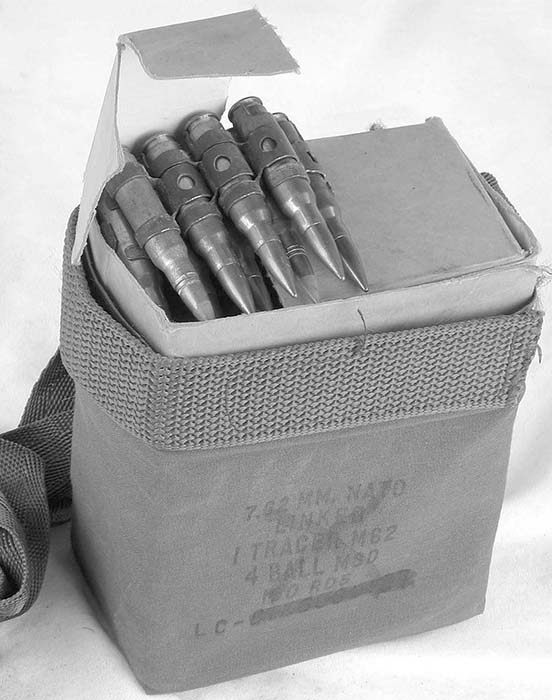
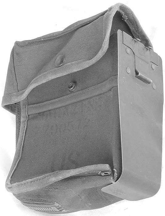
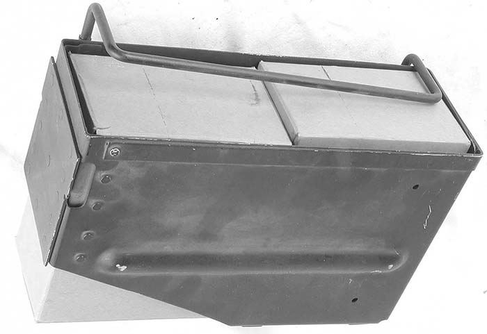
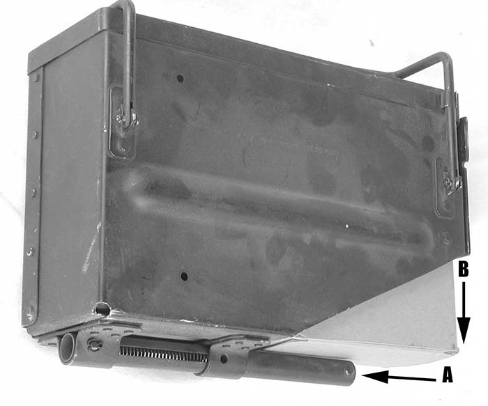
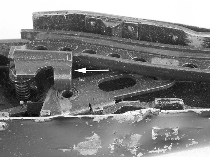
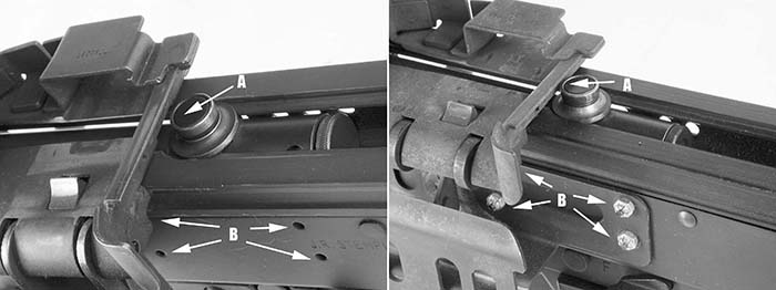
The feed tray assembly is a simple device that serves to hold the linked belt in position while in the feed mechanism, guide the linked ammunition to the cartridge stripping position, and then guide the discarded links out of the gun. The tray itself is a unitized part manufactured from stamped, formed, and welded sheet metal. Into this fabrication are fitted a cartridge holding pawl, and on the M60D variant (and not used with ground gun variants) two belt feed guide spools, or rollers (roller, linear-rotary, PN7269333/NSN3120-00-608-5300) which help to align the incoming linked belt from the fixed ammunition guide chute. In place of these guide rollers on ground guns this location is provided to attach a fixed feed guide plate known as the "bandoleer hanger" (PN 8448414/NSN 1005-00-403-9507).
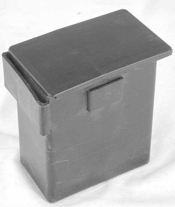
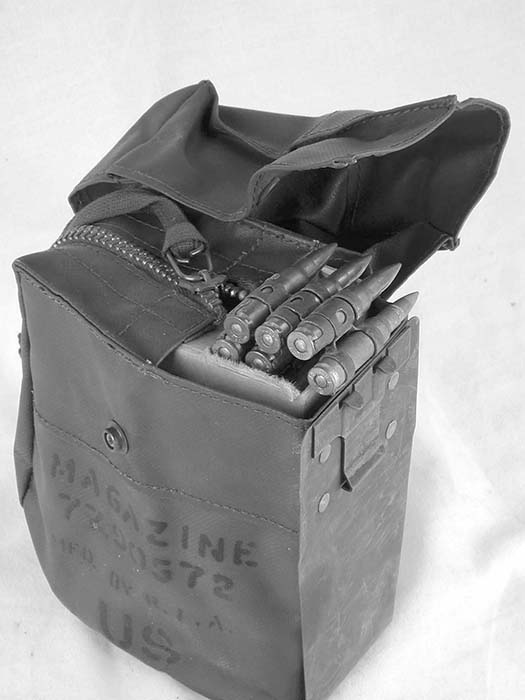
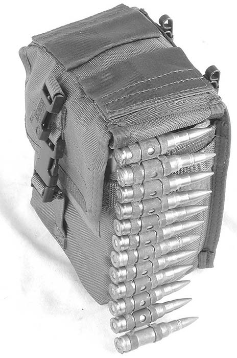
For ground guns, the bandoleer is the common ammunition-carrying container. These bandoleers are disposable and made (in USGI issue) from lightweight cotton fabric with a cardboard insert to provide a measure of form and stability to the linked belt within. They are designed to slip over the "bandoleer hanger" and support the full linked belt for ease of feeding into the gun; they also provide a measure of protection for the belted ammunition to keep it free from contamination. Introduced later was the all plastic (molded polyethylene), snap-on, "100-rd Assault Box." This black plastic box is intended to be a sturdier form of disposable, containerized, ammunition issue packaging. It is issued as a single-use disposable package that snaps onto the same location as the cotton bandoleer, but is designed to withstand significantly more abusive service, including amphibious operations, without failure or the deterioration that was common with standard cotton bandoleers. It has the added advantage of a sliding-lock type of plastic cover that is generally proof against environmental contamination, and which can be positioned to keep "belt flapping" to a bare minimum as the belt is drawn into the feed cover during operation. (Due to the angle the feed mechanism is forced to pull a loose hanging belt into the feed tray at, the section of the belt hanging directly below the feed tray entrance will tend to snap upward and forward in jerking movements as it is fed into the gun. (Minus a proper feed chute as used in vehicle installations, this is an unavoidable nuisance.) Belt flapping of a loose belt can not only lead to possible jamming of the feed mechanism, but also will noticeably mar and scuff the exterior surfaces of the top cover assembly. Use of a suitable belt holding container not only prevents these problems, but also leads to the least strain being imposed upon the actual feed mechanism parts as the belt is drawn more horizontally into the top cover. It is when the gun is fired with an unsupported, loose hanging belt, that the belt feeding pawl(s) are exposed to the most strain, and wear. It is recommended that for maximum service life the gun be fired only with an attached belt holding container at the hanger location, or from an ammunition can when used in a cradle mount. While the plastic 100-rd Assault box is the best of the issue containers, there are several purely commercial equivalents available. Most are fabricated from heavy-duty synthetic fabrics, such as Cordura™, and are in effect a premium quality constructed version of the issue bandoleer. These soft-side containers are probably more durable over time than the plastic boxes, and they are not premium priced accessories as they currently retail for only slightly more than the surplus assault boxes.
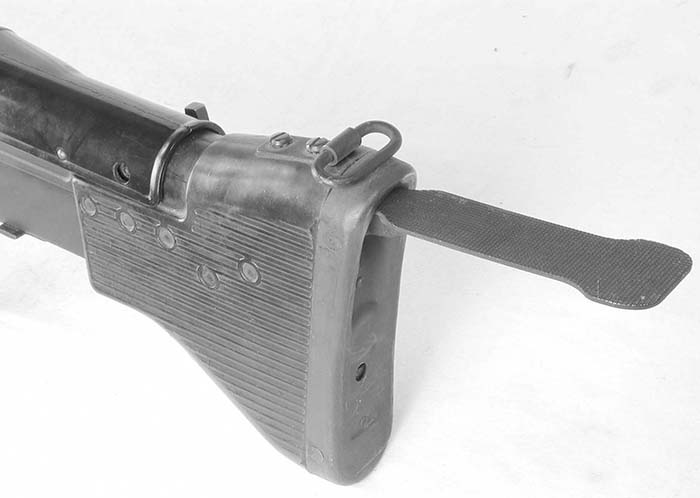
Even with the wide availability of belt holding containers, some operators still choose to run loose belts; if this is the preferred method of operation than, if at all possible, try to arrange for Assistant Gunner to support and help guide the belt horizontally into the gun as it is firing. If an A-Gunner is unavailable, when firing from the prone (bipod supported) or seated (tripod supported) position, the gunner should reach forward and support the free belt section with his left forearm as support and guidance. This situation is perhaps the primary justification for using the hinged buttplate.
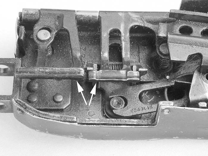
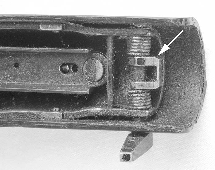
The belt feed pawl fingers are case-hardened ("nitrided", or nitride vapor-bath-hardened) and can be chipped, or cracked, if struck with force. They are extremely durable on the surface of the "fingers" to resist wear from link abrasions, yet brittle along certain lines of stress. In order to avoid this, one should never grab and yank the belt hard in normal use, the only exception to this being if needed to stop a run-away gun. Also, though tempting, additional lubricants should not be used on the feed pawl, as this may lead to failure to feed. The pawl should be clean and dry. Never polish the pawl fingers beyond normal wear of use, for the same reason. With these caveats, failure to feed can usually be traced to improper spring tension in either the feed pawl helical tension spring, or one or both of the cartridge depressor (cartridge guides, front and rear) compression springs. These springs must be at full rating in order to tightly grasp the belt. In rare cases, the pawl itself may have suffered a broken pawl finger. If the belt advances, but then slips backward or falls out, then either the belt holding pawl spring is worn or broken, or the pawl itself is too worn to hold the belt stationary. Feed jams, when all else seems normal, may be the result of a bent or distorted link exit chute, which will cause ejecting links to clog the chute. And one simple, and damaging, operator behavior can cause all of these problems.
The Top-Cover Blues
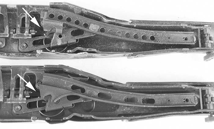
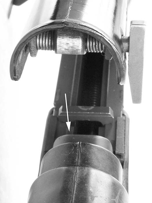
One of the most problematical areas of the basic M60 design was always the manner in which the bolt feed cam actuator drove the feed cam in the feed cover mechanism. The problem, is that neither the cam actuator roller assembly, nor the feed cam itself in the top cover, are provided with any vertical displacement when they are out of engagement relative to each other. And they are always out of alignment except when the bolt is fully retracted and held cocked against the sear. And unless they are aligned and engaged, attempting to move the top-cover can easily damage the components. The only time the top cover on an original M60 can be safely opened or closed is with the bolt locked back. Unfortunately, most operators close the top cover all too often with the bolt forward, which will invariably dent, bend or damage the feed cam (feed arm), or the roller on the feed cam actuator assembly on the bolt. This design deficiency was resolved with the E3/E4 update that employed a spring-loaded feed cam that allowed sufficient vertical displacement for the cover to close safely and latch with bolt forward. With this new cam, when the cover is closed with the bolt forward, it will spring the feed cam track into alignment with the cam actuator roller on the bolt body when the gun is cocked normally. While it is possible to close the cover with the E3 feed cam update installed, it is still a good idea to always open and close the top cover only with the bolt fully locked back as it programs good habits. It is recommended that all variants of the M60 be modified with new E3/E4 feed cover mechanism to help eliminate otherwise costly potential damages.
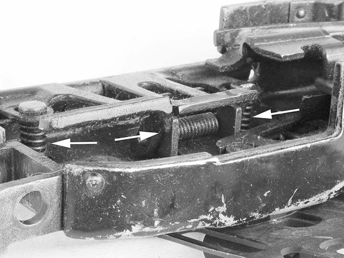
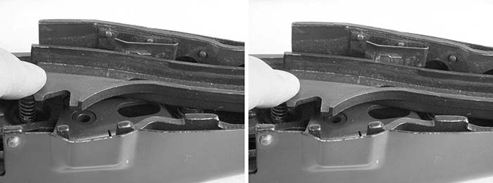
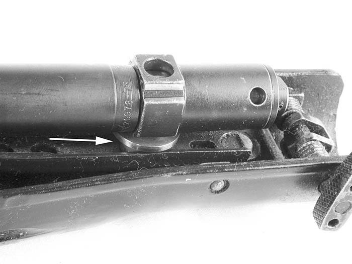
The last area to consider in the feed system, is the feed tray and its relationship to the operating system components. The feed tray is designed to lay flat on the top of the receiver, with a small clearance for the stripping lug of the bolt head to pas through the slot on its bottom face. The bolt must be allowed sufficient forward movement to allow for full chambering of the cartridge head; the feed cam actuator at this full forward dwell will be located directly at the rear support cross member of the feed tray. It is a very close tolerance fit, and if the tolerances milled into the bolt guide rails are a bit off, the cam actuator roller will impact the rear support of the feed tray, denting or bending it. Due to the combination of military and commercial parts used in commercial receivers, this situation is common. This will only happen when the bolt closes on an empty chamber, like when a belt is run dry during firing, or is allowed to close under driving spring tension upon trigger release any other time. If your feed tray shows evidence of this damage, the sheet metal can probably be forced back into shape one time, but changes in operating philosophy should be immediately instituted to prevent repeat or further damages. The only way to prevent this when firing, is to stop firing before the belt runs dry. Learn to watch the belt entering the top cover entrance, and when the last cartridge is seen at the entrance mouth, release the trigger. This will keep 1-3 unfired rounds still in the feed tray, and the bolt will be safely locked back. This single, simple, procedure will also avoid the most serious of the bolt head and barrel locking cam damages as they occur when these components are allowed to close without the cushioning effect of a cartridge case in between for "headspace." (Remember always, safe handling practices, as the gun is still loaded. Engage the safety, unlatch and raise the top cover and clear the remaining short belt section.)
The final mechanism to consider is the top cover latch assembly. The latch and corresponding receiver bridge that it latches into, will last considerably longer if the top cover is not slammed down to latch. The best method to employ is to hold the latching lever fully open, lower the top cover tight against the stop, and release the lever to hold it. Reverse the procedure to open the top cover. The receiver bridge is only a sheet metal stamping, and if the latch recess becomes damaged or distorted, a new bridge will need to riveted into the receiver assembly.
This concludes the basic series for civilian owner-operators for the M60 GPMG system of weapons. Hopefully now, through this series of discussion, you will be better able to use and maintain the valuable and rare investment that these privately owned M60 machineguns represent.
Recommended Manuals and Spares
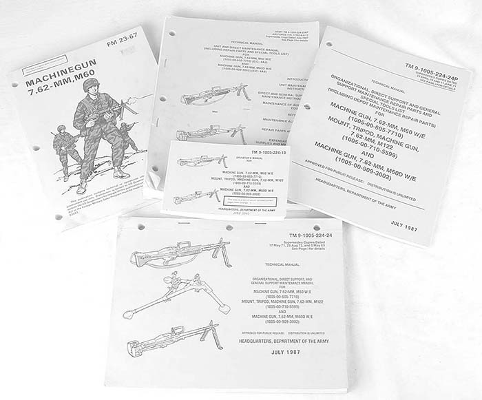
The following military manuals should be utilized in correctly operating and maintaining the M60 series of weapons:
- 9-1005-224-10 Operator's Manual M60 Machinegun (older booklet style Field Operational manual for the M60 ground gun)
- FM 23-67 Machinegun, 7.62 MM, M60 (an excellent Field Operational manual for the M60 ground guns; includes gunnery instructions)
- TM 9-1005-224-24(or -23&P) Technical Manual, Unit and Direct Support Maintenance Manual (covers all variants except the new M60E3, and includes M2/M122 tripod)
- TM 9-1005-224-24P Technical Manual, Organizational, Direct Support and General Support Maintenance Manual Repair Parts and Special Tools Listing
The following basic spare component parts are highly recommended for maintaining the M60 series of weapons. This constitutes only a most basic list of the most commonly required parts. Obviously, with M60 parts getting scarcer and more expensive, a prudent owner will acquire all the spare parts he can locate.
- pin, bolt plug retaining PN 7792920
- extractor, cartridge PN 7790907
- plunger, extractor, PN 269083
- pin, firing PN 11010376
- sear, PN 7269209
- spring, sear, helical compression PN 7269211
- washer, key, gas cylinder PN 7269035
- pawl assembly, feed cam PN 7269120
In addition, you will likely be well served by obtaining at least one spare bolt body, and one spare operating rod assembly. Several spare driving springs are also recommended.
The last and final installment of this series will depart from the current format slightly as it will describe detailed repair methods for commonly seen problem areas using techniques and information that are more appropriate to the civilian realm than the official methods and recommendations shown in the original USGI repair and service manuals. This departure is a consequence of the fact that certain methodologies and techniques used by the US Military infrastructure are almost now impossible to obtain or perform due to the dwindling lack of support for this weapon system.
This article first appeared in Small Arms Review V7N6 (March 2004)
and was posted online on September 6, 2013
Source: https://smallarmsreview.com/the-civilian-m60-machinegun-owners-guide-part-v/
0 Response to "M60 Diagram Feed Tray and Hanger"
Post a Comment